How to determine the gcode offsets in X and Y for the Z probe and toolheads, with Klipper.
This is done with the help of a cheap Digital Microscope from Aliexpress, costing in 2024 only 14 Euro, and Klipper with some simple macros.
In this case toolhead T0 is the reference because the Z probe is attached to it. The Z probe offset and other toolhead offsets are calculated using T0 as a reference.
Due to the manual focus of the microscope, all Z-offsets should be set to a fixed value, if possible at 0.
Start with the "Pre conditions" then continue with one of the others: 'Z probe XY offset', 'Toolhead XY offset' or 'Verify a configured Toolhead XY offset'.
The toolhead move distance increments in X and Y are available in steps of 0.1, 0.01 and 0.001 .
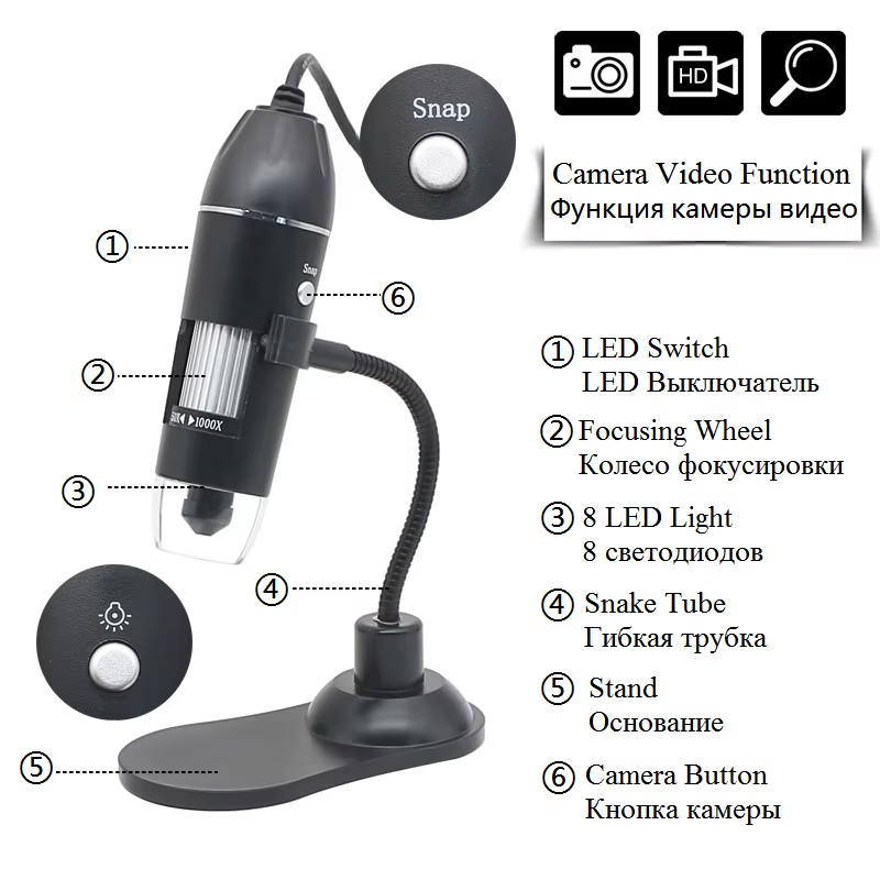
The digital microscope:
- It has a stable pedestal,
- It is available as webcam within Klipper,
- It has the crosshair enabled in any color or size.
The gcode offsets of all toolheads are set to 0 in the configuration file with "SET GCODE OFFSET X=0 Y=0".
The toolhead with the attached Z probe is loaded.
All axes are homed (remove the microscope first !!).
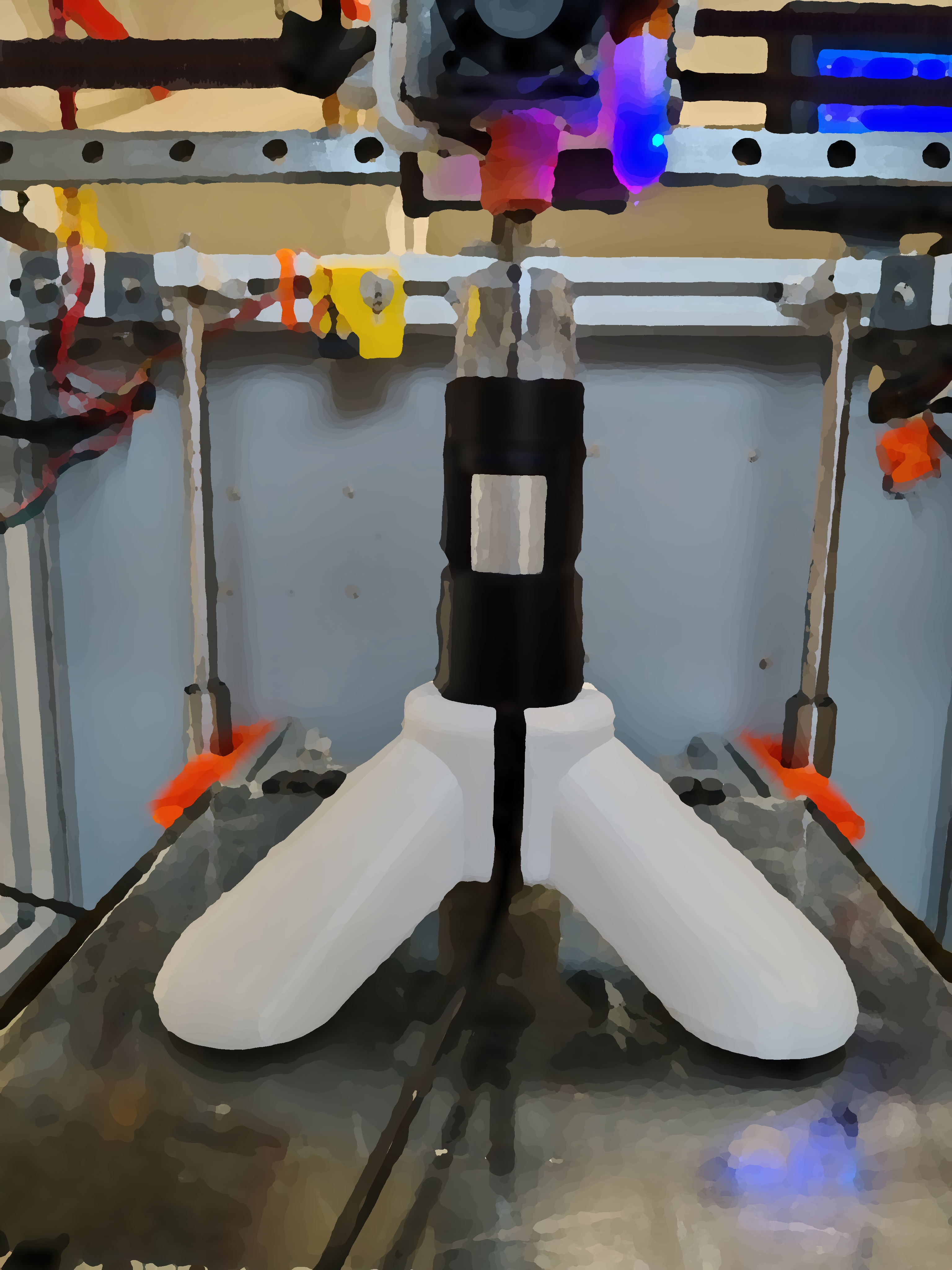
Adjust the toolhead or build plate height Z, so the microscope, with pedestal, fits under it with a small gap. Position the microscope on the build plate so that the nozzle is close to, or in, the crosshair.
Z Probe XY offset
If needed, change the microscope's crosshair size to fit the nozzle or Z probe.
Using the Toolhead move distance increment buttons, accurately move the nozzle into the center of the crosshair, then push "SET REFERENCE POINT".
Move the toolhead, with the distance buttons, to any position in X and Y and then push "GOTO REFERENCE POINT".
The nozzle should return exactly to the crosshair center. If it does not match exactly then, probably, the pedestal has moved.
Using the move distance increment buttons, accurately move the probe into the center of the crosshair and then push "CALCULATE OFFSET".
The calculated values are displayed in the Klipper console.
Verify the calculated offset is correct by pushing "GOTO REFERENCE POINT" and then "GOTO OFFSET". If adjustments are needed repeat one of the previous 2 steps.
Add or verify the offsets to the Z probe's configuration file. This may require the axes to be homed again so remove the microscope !!
Toolhead XY offset
If needed, change the microscope's crosshair size to fit the nozzle opening
With the move distance increment buttons, accurately move the nozzle of the toolhead T0 into the center of the crosshair then push "SET REFERENCE POINT".
Move the toolhead T0, with move distance increment buttons, to any position in X and Y and then push "GOTO REFERENCE POINT". The nozzle should return exactly to the crosshair center. If it does not match exactly then, probably, the pedestal has moved.
If needed repeat steps starting at step 1.
Switch from toolhead T0 to T1.
With the move distance increment buttons, accurately move the nozzle of toolhead T1 into the center of the crosshair and then push "CALCULATE OFFSET".
The calculated values for T1 are displayed in the Klipper console.
Verify the calculated offset for toolhead T1 by:
- switch to toolhead T0 and push "GOTO REFERENCE POINT".
- switch to toolhead T1 and push "GOTO OFFSET".
If the Z probe is attached to toolhead T0 make sure its loaded because after the next step the axes have to be homed.
Replace in the configuration file the zeros for the gcode offset of T1 with the calculated values as displayed in the console at "SET GCODE OFFSET X=0 Y=0".
Remove the microscope from the build plate and home all axes.
Verify a configured Toolhead XY offset
If needed, change the microscope's crosshair size to fit the nozzle opening.
Remove the microscope from the build plate and home all axes.
Adjust the toolhead or build plate Z height and position the microscope on the build plate so that the nozzle is in the crosshair.
With the Toolhead move distance increment buttons, accurately, move the nozzle of the toolhead T0 into the center of the crosshair and then push "SET REFERENCE POINT".
Move the toolhead T0, with move distance increment buttons, to any position in X and Y and then push "GOTO REFERENCE POINT".
The nozzle should return exactly to the crosshair center. If it does not match exactly then, probably, the pedestal has moved.
If needed repeat steps starting at step 3.
Switch from toolhead T0 to T1 and then push "GOTO REFERENCE POINT" and verify the nozzle is in the crosshair.
Switch from toolhead T1 to T0 and then push "GOTO REFERENCE POINT" and verify the nozzle is in the crosshair.
If the nozzles were not, more or less, exactly in the crosshair then repeat "Toolhead XY offset".
Switching between toolheads, or moving the build plate up and down, may result in a small move of the pedestal.
Preventing these small moves is essential. Use tape, a glue stick, magnets, or "your own solution" to fixate the pedestal.
To prevent small movements of the pedestal on the glass plate, I glued rubber bicycle tire patches on the pedestal soles.
Fixate the USB cable of the digital microscope to the build plate with a clamp.
The Microscope: model MGH1000, with USB, zoom 50x-1000x, with led lights, manual focus.
The used home-build 3d printer has 2 toolheads and a 3D Touch Z-Probe. The brass nozzle of T0 is 0.4 mm and the nozzle of T1 is dark coated and 0.5 mm.