Allen keys: you need M1.5, M2.5, M3 and M4 mm Allen keys.
The parts stated in the manual sections may not comply with the parts you received or ordered. Sometimes parts are missing.
The last photo of a building section may show how it should have been assembled, thus... read, and
read per step the complete instruction before you start to build.
The kit provides (almost) all you need but that does not mean you just have to put them together; some crafts, tinker, tweaking, tuning is needed.
All metal parts have sharp edges and are not painted so there is work to do.
Take your time, if possible use a work space where you can leave all parts on the table when you stop building.
The strength of the 3d printed parts (all black parts) is that of a penny waffle (or egg) and the print-quality is in some places poor.
Use the short 70 cm USB cable provided with the kit. Longer cables may lead to connection problems
The cable carrier seems a good option but it is not (see photo's under "16 Cable Carrier").
It is designed to be used with a compact direct drive or bowden setup. The filament sometimes get cought in it.
DO NOT apply any kind of lubricant until all assembly steps are done (no greasy hands + parts) and you start with the software/calibration.
Once the Prusa is up and running the first goal will be to make better parts and adding protection for the wiring against the sharp metal edges of the frame.
-
P3Steel Assembly steps as found on www.kitprinter3d.com (september 2015)
- Frame
Nuts and bolts: F
Additional: Drill 2 holes 3mm diameter in AC01 (middle of left/right side)2016-11-29: Do not do that, the x-carriage can get stuck on these bolts.
DO NOT tighten the bolts/nuts at both AC08's (left and right). It is much easier
to mount the Z320 rods into AC07 and AC08 in step 5 when you remove AC08.
MISSING: parts 2 x AC18 and AC17.
- Mechanics - Y axis
Nuts and bolts: F
Additional needed: 8 washers 3 mm to bridge a 1 mm gap between AC11 and AC12 when LM8UU is mounted.
I do not know why but there are no provisions to keep the Y341 rods fixed in the frame (AC05).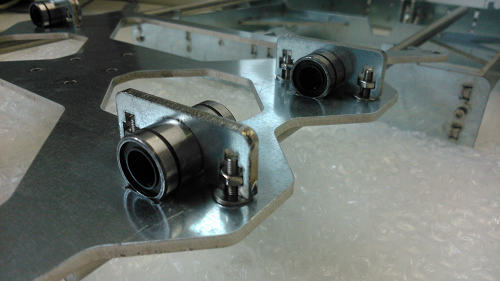
- Mechanics - X axis
Nuts and bolts: X
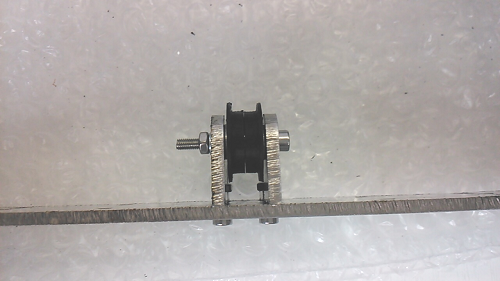
Additional added 2 washers 3 mm to pulley assembly to reduce the tolerance.
The black 3d printed parts crack easy, so handle carefully.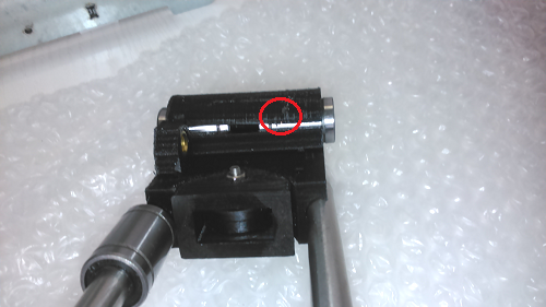
- Mechanics - Y axis motor
Nuts and bolts: Y
Nuts and bolts: F
Additional added 2 washes 3 mm to pulley assembly to reduce the tolerance
and a 3 mm locking ring for the nut.
- Mechanics - Z axis motors
Nuts and bolts: Z
EASIER: Remove both AC08's, mount the Z320 rods in the AC07's, mount theX axis assembly on the
Z320, mount both AC08's and now tighten the bolt/nut.
NOTE: one Z320 rod was 323mm.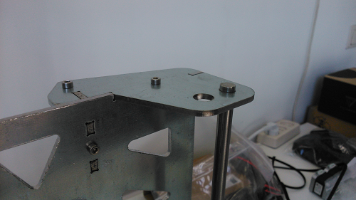
- Mechanics - X axis motor
Nuts and bolts: X
NOT USED: end stopper bolt (where ? Step 10)
- (B) Extruder motor (E3D V6)
Nuts and bolts: E
Check www for the E3D V6 assembly (comes with glassed thermistor).
- Heated bed
I got an aluminium heat bed (which is needed for auto leveling) so some parts are missing.
Do step 10 first or you have to remove the bed in step 10.
Nuts and bolts: H
MISSING: (glass panel, 4 binder clips,) thermistor for the heat bed.
MISSING: clear instruction how to route the cables. Glass panel + clips: the aluminium bed is 3 mm thick which could be enough to print on.
- The electronic board
Nuts and bolts: B (why only 3 and not 4 polyamide bolts/nuts...?)
I ordered a SAV MK1 and there is no assembly page for it.
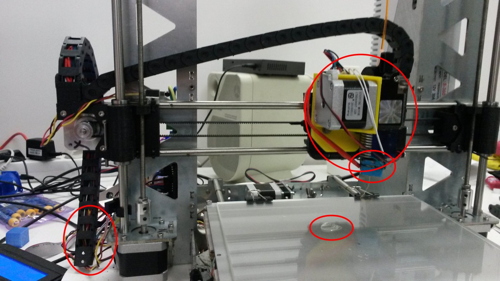
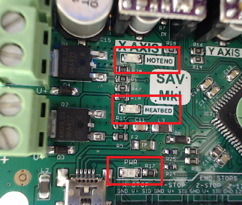
The board has 3 leds: HEATBED, HOTEND and PWR, see red rectangles, to indicate what ? That the current flows to them.
See step 11 on how to position the board.
- The Endstops
Do this step before 8 or you have to remve the heated bed.
It is my lack of knowledge at this point but why is there only 1 stopper, and not 2 stoppers, for X, Y and Z ?
Nuts and bolts: Y + X
- Connections
Although there are photos how to connect the cables to the electronic boards there are NO instructions on how to
to lay them through the metal frame. With so many sharp edges that is asking for problems.
I bought the E3D V6 with ventilator. The ventilator must have permanent power and you cannot shut the power off unless the heaterblock is at almost room temperature. If you don't you risk clogging/bulg forming in the teflon tube inside the heatsink. I had that problem.
- Software
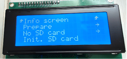
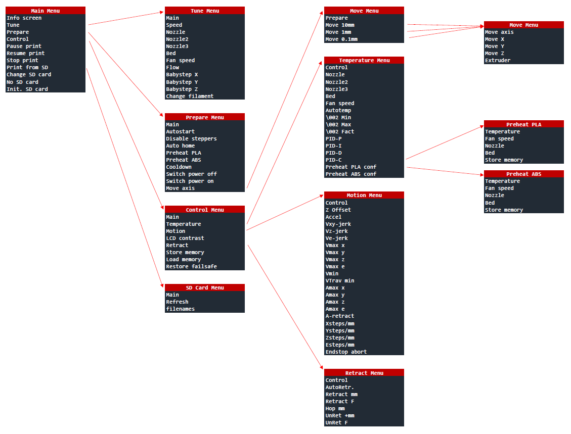
The SAV board comes preprogrammed with some special Kitprinter3D software. Put the power on (next step) and LCD display shows a page.
Go into the 'Prepare page' submenu 'Move Axis' and verify that X, Y, Z (and extruder) motor can turn.
The extruder motor only turns when the hot end (and heatbed ?) is at its temperature (submenu 'Preheat PLA').
Temperatures are displayed on the LCD info panel.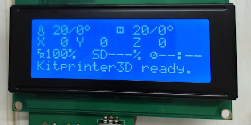
STEP 1: download the Arduino 1.0.6 IDE.
Teensyduino 1.24 supports Arduino versions 1.0.6 and 1.6.1 and 1.6.3 and 1.6.4 and 1.6.5.-
The manual states "NEXT DIRECTIONS WILL HELP YOU TO SET UP THE DEVELOPMENT ENVIRONMENT USING THE IDE (ARDUINO 1.05 OR LATER)."
but also "Download the development Arduino 1.0.5 environment." which is not supported by Teensyduino.
I ignored 1.0.5 because 1.6.3 is later and downloaded Arduino 1.6.3 and got errors, see below.
STEP 2: No additonal libraries needed. So I clicked "Next" without selecting anything.
STEP 3: The teensy hardware directory is c:\Program Files\Arduino\hardware\teensy\avr
Copy the the *.txt files from the zip direcory At90usb1286txt_SAV_MkI to that directory.
When launching Arduino the 4 files stated in the manual are under TOOLS -> Board "Arduino one"."Download the Marlin's configuration following the previous table and open it from Arduino IDE." Yes, but how ?
Open the Marlin zip file and copy the directory called "marlin" to your harddisk. Start Arduino IDE and go to Menu File, submenu Open. In the file browser go to the "marlin" directory and open file "Marlin.ino".
I connected the power and USB able to the board, removed the jumper and pushed the button... nothing happens only I hear Windows detects something. Open menu Tools submenu Ports. In my case there is besides COM1 a COM4 port so I selected COM4. Then Menu File submenu Upload. After a few moments I get the message "Error compiling" and saying:In file included from Marlin.h:23:0,
from BlinkM.cpp:5:
pins.h:1876:2: error: #error Oops! Make sure you have 'Teensy++ 2.0' selected from the 'Tools -> Boards' menu.
#error Oops! Make sure you have 'Teensy++ 2.0' selected from the 'Tools -> Boards' menu.
^
Error compiling."I forgot to select [BootloaderCDC]SAV-MkI from Tools-->Board. So I selected that too... and now it says
"Arduino: 1.6.3 (Windows 8.1), TD: 1.24, Board: [BootloaderCDC]SAV-MkI
Cannot run program "C:\Program Files\Arduino/{build.toolchain}{build.command.g++}": CreateProcess error=2, The system cannot find the file specified
This report would have more information with
"Show verbose output during compilation"
enabled in File > Preferences.
"
Ok, this ends here with Arduino 1.6.3. I switch to 1.0.6 (and not 1.0.5 because Teensyduino does NOT support 1.0.5).
At this point also read 12.2.1 because you have to get a special library for the LCD panel.
STEP 2: No additonal libraries needed. So I clicked "Next" without selecting anything.
STEP 3: The teensy hardware directory c:\Program Files\Arduino\hardware\teensy\ is now correct.
If you have the SAV 3D LCD panel read http://reprap.org/wiki/SAV_3D_LCD and install the library V1.2.1.
There is a new 1.3.1 version that supports all kind of electrical interfaces but you do ot need that version."Download the Marlin's configuration following the previous table and open it from Arduino IDE." Yes, but how ?
Open the Marlin zip file and copy the directory called "marlin" to your harddisk. Start Arduino IDE and go to Menu File, submenu Open. In the file browser go to the "marlin" directory and open file "Marlin.ino" and... a warning pops up "Moving" saying that the Marlin.ino file needs to be inside a sketch folder named "Marlin". I pressed OK. In menu Tools select COM4 and [BootloaderCDC]SAV-MkI. I select menu File and Upload and...This report would have more information with "Show verbose output during compilation" enabled in File > Preferences.
Arduino: 1.0.6 + Td: 1.24 (Windows NT (unknown)), Board: "[BootloaderCDC]SAV-MkI"
Marlin:33: error: Configuration.h: No such file or directory
Marlin:34: error: pins.h: No such file or directory
This is not going smoothly.
The files are not missing. They are in the marlin directory.
The zip file contains a "marlin" directory and that has to be a "Marlin" directory.
Also make sure the directory path does not contain spaces or "-" characters.
So I moved the marlin directory to "d:\Prusa\Marlin", opened the Marlin.ino file and with menu File and Upload and... YESBinary sketch size: 121,196 bytes (of a 122,048 byte maximum)
Found programmer: Id = "LUFACDC"; type = S
Programmer supports buffered memory access with buffersize=256 bytes.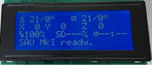
- Power supply
The english page is in spanish but it is not difficult to attach the PSU 30A to the frame and connect the powercables.
MISSING: powercable from PSU 30A to the SAV MK1 board.
Nuts and bolts: P3
- Calibration
TOOLS: Phillips ceramic screw driver Who has that ? This tool should be included in the kit.
I used 1.8mm screw driver and disconnected each time the power before turning the potentiometer of DRV8825.
BUY A CERAMIC SCREDRIVER. The potentiometer is so sensitive that alone touching changes it to some bad value.
TIP: Use a permanent marker to mark the potentiometer so you can see when you turn it.
TIP: Don't stop tuning when the motor turns (moves freely and at ease ?), stop when the motor turns and is at its quietst !!
"Open Printrun"... nice you mean pronterface or pronsole ? It is pronterface.
After you have used it with Arduino reset your PC before using Printrun .
Printrun looses its connection with the Prusa frequently and then you have to reset your PC and the Prusa. This is realy annoying. (See Problems/solutions: the crashes are a Windows 10/Nvidia problem).
Unfortunatly the USB interface is not very stable and drops very easy:Connecting...
Printer is now online.
[ERROR] Can't read from printer (disconnected?) (SerialException): call to ClearCommError failed
[ERROR] Can't write to printer (disconnected?) (SerialException): WriteFile failed ([Error 22] The device does not recognize the command.)
[ERROR] Can't write to printer (disconnected?) (SerialException): WriteFile failed ([Error 22] The device does not recognize the command.)
[ERROR] Can't write to printer (disconnected?) (SerialException): WriteFile failed ([Error 22] The device does not recognize the command.)
[ERROR] Can't write to printer (disconnected?) (SerialException): WriteFile failed ([Error 22] The device does not recognize the command.)
[ERROR] Disconnecting after 4 failed writes.
Disconnected.
See on http://smoothieware.org/pronterface for some hw improvements
BUT the real thing that helped was to de-install the Teensyduino driver (Device Manager -> Ports -> Teensyduino) completely for the USB port and let Windows 10 use its own USB Serial Device driver. This could become a problem when installing new software. After installing CURA I had nothing but problems.Now I conclude its the used 1 meter USB cable. The connection can only work with the short USB cable (70 cm) which is included in the kit. Using longer cables (1 meter) just causes problems.I re-installed Teensyduino.I understand that the motors torque is contolled with the potentiometer. Some motors work right away and some do not. The instructions don't state what to do if the motors turn right away. Should you start at the point of not turning ? In my case the extruder motor turned without adjusting the potentiometer so what should I do with "..but once it begins to rotate, increase 1/2 turn more the screw" ?
- LCD controller frame
I have an LCD panel with the SAV MK1 but parts 2 x AC18 and AC17 are missing and the LCD panel will not fit part AC17.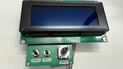
- Cable carrier
The cable carrier is design flaw. It does not fit well at all with 'Gregs' extruder. It seems to be for a bowden extruder setup or a direct drive.
The extension cable for the ventilator needs some force to fit to the ventilator-connector.
Some cables (heater cartridge) may be too short, so think carefully how you route the cables.
The cable carrier limits the maximum print height because of the extruder motor (see step 7A).
The cable carrier can be easy split by twisting it at the desired chain link.
I used 26 chain-links for the X-AXIS assembly and 19 chain-links along the left Z-AXIS.
Note there is not enough space for the X-motor at the C-Frame printed part (and the extruder will not reach the heated bed).
If the cable carrier is mounted on the X-axis assembly (horizontal) as suggested you will loose at least 4 cm printing height.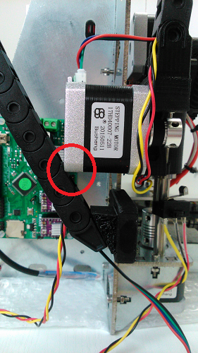
- Autolevel
The Z-12V interface is located right of the Z-STOP connector on the SAV MK1 board.
The connector-pins and wiring needs some soldering. Unfortunatly the plastic covered wires are a bit to thick for black housing.
When you have soldered the pins use a 1-2mm thick needle to push the pins for the last 2-3 mm into the housing.
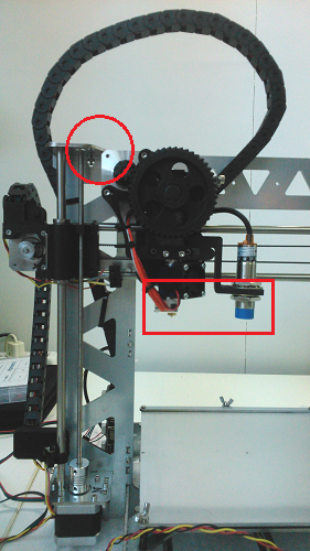
I do not know why but the sensor is ~6.5 cm from the nozzle. There is at least 2 cm not needed space.Download the software for the Autolevelling. It is for DRV8825. Why a different software download compared to Step 13 ? I used this version for step 13.
The manual does not state which arduino libraries/hardware you have to add. Arduino 1.0.6 does that mean those in arduino_1.0.x and arduino_1.x.x ???
Both seem logical so I did that and replace the existing libraries.
The error I get:
This report would have more information with "Show verbose output during compilation" enabled in File > Preferences.
Arduino: 1.0.6 + Td: 1.24 (Windows NT (unknown)), Board: "[BootloaderCDC]SAV-MkI"
In file included from ultralcd.cpp:41:
ultralcd_implementation_hitachi_HD44780.h:198: error: 'LiquidCrystal_SR' does not name a type
/ultralcd_implementation_hitachi_HD44780.h: In function 'void lcd_set_custom_characters()':
ultralcd_implementation_hitachi_HD44780.h:366: error: 'lcd' was not declared in this scope
/ultralcd_implementation_hitachi_HD44780.h: In function 'void lcd_implementation_init()':
ultralcd_implementation_hitachi_HD44780.h:404: error: 'lcd' was not declared in this scope
/ultralcd_implementation_hitachi_HD44780.h: In function 'void lcd_implementation_clear()':
ultralcd_implementation_hitachi_HD44780.h:417: error: 'lcd' was not declared in this scope
/ultralcd_implementation_hitachi_HD44780.h: In function 'void lcd_printPGM(const char*)':
ultralcd_implementation_hitachi_HD44780.h:425: error: 'lcd' was not declared in this scope
/ultralcd_implementation_hitachi_HD44780.h: In function 'void lcd_implementation_status_screen()':
ultralcd_implementation_hitachi_HD44780.h:485: error: 'lcd' was not declared in this scope
/ultralcd_implementation_hitachi_HD44780.h: In function 'void lcd_implementation_drawmenu_generic(uint8_t, const char*, char, char)':
ultralcd_implementation_hitachi_HD44780.h:633: error: 'lcd' was not declared in this scope
/ultralcd_implementation_hitachi_HD44780.h: In function 'void lcd_implementation_drawmenu_setting_edit_generic(uint8_t, const char*, char, char*)':
ultralcd_implementation_hitachi_HD44780.h:655: error: 'lcd' was not declared in this scope
/ultralcd_implementation_hitachi_HD44780.h: In function 'void lcd_implementation_drawmenu_setting_edit_generic_P(uint8_t, const char*, char, const char*)':
ultralcd_implementation_hitachi_HD44780.h:677: error: 'lcd' was not declared in this scope
/ultralcd_implementation_hitachi_HD44780.h: In function 'void lcd_implementation_drawedit(const char*, char*)':
ultralcd_implementation_hitachi_HD44780.h:732: error: 'lcd' was not declared in this scope
/ultralcd_implementation_hitachi_HD44780.h: In function 'void lcd_implementation_drawmenu_sdfile_selected(uint8_t, const char*, const char*, char*)':
ultralcd_implementation_hitachi_HD44780.h:746: error: 'lcd' was not declared in this scope
/ultralcd_implementation_hitachi_HD44780.h: In function 'void lcd_implementation_drawmenu_sdfile(uint8_t, const char*, const char*, char*)':
ultralcd_implementation_hitachi_HD44780.h:766: error: 'lcd' was not declared in this scope
/ultralcd_implementation_hitachi_HD44780.h: In function 'void lcd_implementation_drawmenu_sddirectory_selected(uint8_t, const char*, const char*, char*)':
ultralcd_implementation_hitachi_HD44780.h:786: error: 'lcd' was not declared in this scope
/ultralcd_implementation_hitachi_HD44780.h: In function 'void lcd_implementation_drawmenu_sddirectory(uint8_t, const char*, const char*, char*)':
ultralcd_implementation_hitachi_HD44780.h:807: error: 'lcd' was not declared in this scope
Ok, I need LiquidCrystal from https://bitbucket.org/fmalpartida/new-liquidcrystal/downloads V1.2.1 and replaced it.
Binary sketch size: 121,528 bytes (of a 122,048 byte maximum)
Found programmer: Id = "LUFACDC"; type = S
Programmer supports buffered memory access with buffersize=256 bytes.
The instruction states: "The sensor is able to detect the aluminum bed from 1mm-2mm.". That is NOT true, its closer to 5-6 mm.
Check this video of Thomas Sanladerer about bed leveling. Check the instructions starting at 9:00. The video uses a heated bed/extruder the manual does not; in the video the extruder does not touch the bed but the manual states "...until it touches the aluminum bed.". The assembly manual states "The sensor is able to detect the aluminium bed from 1mm-2mm. Take this into account to calculate the distance between the nozzle and the sensor." but there is no instruction on how to do that.This is what I did.
The autoleveling sensor replaces the Z-axis stopper, thus when the (not heated) nozzel is just touching the bed the indicator of the sensor should just lit. And when you put a paper between the (heated) nozzel and bed it should not be lit. This can be verified with the "M119" command which reports the endstop status.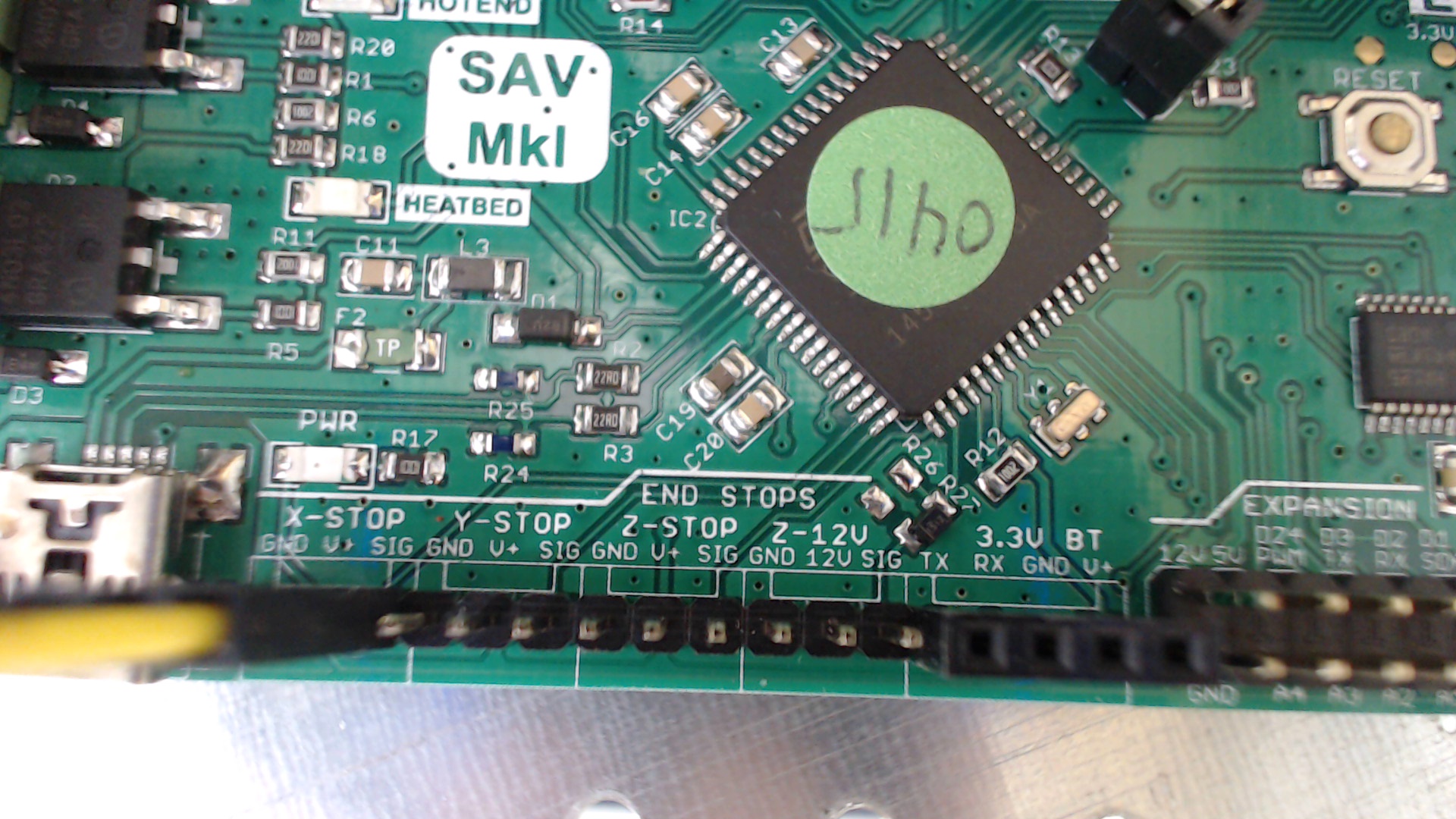
- MISSING STEP: How to level the heated bed.
Bed levelling should be performed when the bed and extruder nozzle are at its operating temperature for the filament.
Before you start: - put the printer on a flat surface
- the distance on left and right side the distance from AC08 to the upper level of X-Motor and X-Idler should be the same in mm.
- the distance on left and right side the distance from the flat surface to the upper level of X-Motor and X-Idler should be the same in mm.
- the heated bed wing nuts should be tightened completly and
- the distance between the heated bed and the flat surface should be the same at all 4 corners
- the Z stopper should stop the extruder 2-3 mm above the heated bed (all 4 corners) when the heated is OFF and when heated is ON (extruder included).
- When the bed and extruder are at the filament temperature position with Printrun the extruder at each of the 4 corners of the bed and adjust in each corner the bed height turning the most close by wing-nut so that a normal piece of A4 paper slides between (both heated) bed and nozzle.There is an easier way" download CURA and use the bed levelling wizard.
- MISSING STEP: before the first print...
Do some 10 to 15 bed-levelling excercises until you fully master it then go for a 'dry' print run.
A 'dry' print run is a print run without filament. Its a final check that all works correctly.
I noticed that X, Y and extruder motor really get burning HOT !! and stumbled into the problems as described below. - MISSING STEP: the first print...
- Done: The Y-AXIS motor sometimes turns and then stops turning, or it does not turn at all.
After replacing the Y's Pololu DRV8825 with a Stepstick DRV8825 the problem seems solved... but no the problem returns. I switched motors, cables, calibrated drivers and nothing worked until I put a little pressure on the aluminum cooling block of the Y's DRV8825 and it worked !! Looks there is a problem with the board, putting some presure on upper right corner of the board has the same effect. Permanent pressure was applied via a cable tie. This means there is either some bad soldering or the board has a broken wire.
After contact with the manufactor (Francisco Malpartida) the SAV MKI is an its way back to Spain for repair or replacement (board was sent end oktober 2015). I am still waiting for the board to return which will be somewhere in 2016 according to the last mail of december 2015. When will I get the board back ? I prepared myself for the famous Spanish "Manjana" and bought a second board which I use now.
February 2016: The board is back and Francisco could not find any problem. I put a new set of Stepstick DRV8825 in the board then tuned every Stepstick DRV8825's potentiometer until that motor was QUIET when doing its function and ran a 2 hour during print job for a 20mm cubicle. Its now a much quieter 3d printer and I did not have a fialing print job... the Y-motor is also much cooler.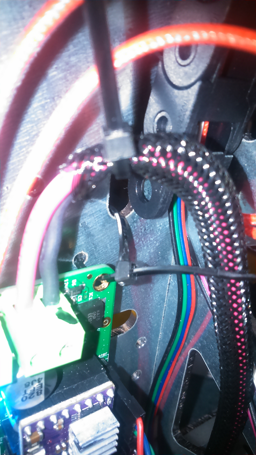
- Done: Printrun (pronterface) and/or the USB connection are very unstable.
I changed to RepetierHost at http://www.repetier.com/download-now/ plus a short USB cable and the USB problem seems solved. This is a Windows 10 - Nvidia problem. My PC has a Nvidia graphics card and the display driver keeps crashing. After changing to an Imac the problem no longer exists. The Nvidia display driver is also the cause of Cura crashes which I had also with Windows 10 - Nvidia. - Not solved: After a dry-run (no filament) the autolevelling failed at the back of the bed and the extruder nozzle scratched the heatbed.
The indicator (led) of the autolevelling sensor did not lit. Why... ? I removed the autolevelling and installed the correct software without autoleveling. See next point for anti-scratch of the heatbed prevention. - Done: DO NOT print directly on the aluminium heated bed.
Any printed part is 'glued' to the bed (despite kapton or tape) and to remove it from the bed I had to remove the heatbed. The solution is to buy several 20*20 cm aluminimm plates (3mm thick) and some heatbed clamps (4). Put one plate on top of the aluminium heated bed and fix with the clamps. Protect the underside of the heatbed against the sharp edges of the clamp with some layers of kapton tape or use a cardbord with the size of the heatbed (works well). After printing you can swap plates, start printing again and then remove the 'glued' part from the plate. This way you will not damage the heatbed but only a cheap plate. - Done: The Y motor keeps making noises and growls when the heatbed is close to the motor, see also next point.
Turns out that the height (Z-axis) of Y belt, Y pulley, heatbed (belt attach points) and Y motor are not in line. They have to be in line between pulley-heatbed and heatbed-Y motor. I lowered the belt attachment to the heatbed on the Y motor side some 6 mm and now its much better. - Done: Y Belt tension.
I was getting some kind of wave-pattern on left and right side of the printed parts in the movement direction of the Y-axis. Turned out the belt tension was not tight enough. If you see the Y belt vibrating when the heatbed moves then it is not tight enough. If the belt tension is too tight the Y motor will make humming noises. - Done: Y-rod stopper plates (4).
The Y-rods are not blocked by anything, with this plate they are stopped. I drilled 2 holes of 3 mm for each plate. Freecad: Y_rod_stopper.fcstd, or ready to use Y_rod_stopper.stl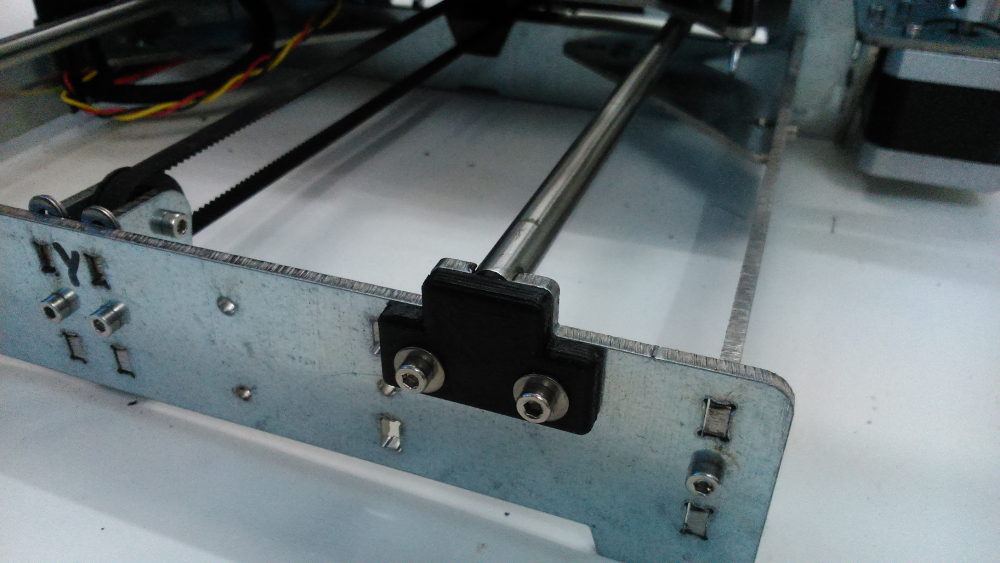
- Done: Calibrate extruder feed.
When your prints keeps looking bad the printer may extrude too much or not enough, check this page http://reprap.org/wiki/Print_Troubleshooting_Pictorial_Guide#Material_Feed and these videos "RepRap 101: Setting your 3D printer's extrusion" https://www.youtube.com/watch?v=w_Wb0i0-Qvo and https://www.youtube.com/watch?v=cnjE5udkNEA - Done: Replace linear bearings LM8UU's X and Y axis (2016-03-26).
After some 5 months of usage (every weekend 3/24) the X carriage (extruder) and Y carriage (heatbed) had to much tolerance. I could wiggle heatbed and extruder easy. After replacing the 7 LM8UU's the problem is over for now. I am afraid the cheap LM8UU's (4 rows of balls) are not up to it. Next time I will replace them with bronze buschings. - Done: How to setup Cura:
https://all3dp.com/3d-slicer-settings-beginners-8-things-need-know/" - June 2016, Open: All stopped, melted power connector and wires:
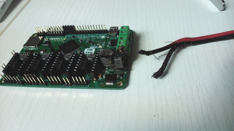
I had nothing but problems with the printing of PETG. Layers were not aligned or better showed alignment jumps.
Check this page: https://all3dp.com/common-3d-printing-problems-and-their-solutions/ and http://reprap.org/wiki/Print_Troubleshooting_Pictorial_Guide.I lubricated the X and Y rods and adjusted the X and Y drivers. That seemed to help. I did notice some 'burned plastic' smell but I thought it was the printing and ignored it. After printing stopped completly I discovered that one of the screws of the power connector had loosened... and connector and wiring were burned. Luckily I have a spare board. I hope I can repair the damaged board.
- June 2016, Open: Filament jamming in extruder with PETG:
In order to print PETG and if your hot-end can deliver high temeperatures set the values in Configuration.h to:
#define HEATER_0_MAXTEMP 275
#define HEATER_1_MAXTEMP 275
#define HEATER_2_MAXTEMP 275
#define BED_MAXTEMP 150
PETG causes the glass plate to flake due to temperature changes and the sticky PETG. I can hear 'cracks' when it cools down from 82 degrees Celcius to room temperature. - September 2016, Close: Filament jamming in extruder with PETG:
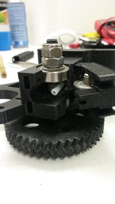
This is caused by the filament not passing straight along the hobbed bolt. A small miss-alignment causes the filament to rotate and get jammed below or above the bolt. I pushed a piece of filament to align the idler to the hobbed bolt. Somewhere on the internet I found the folowing additional solution: use an extended teflon tube from heatbreak until it reaches the idler. At the hobbed bolt remove half of the tube so the filament can still be pushed through the tube.
This worked very well.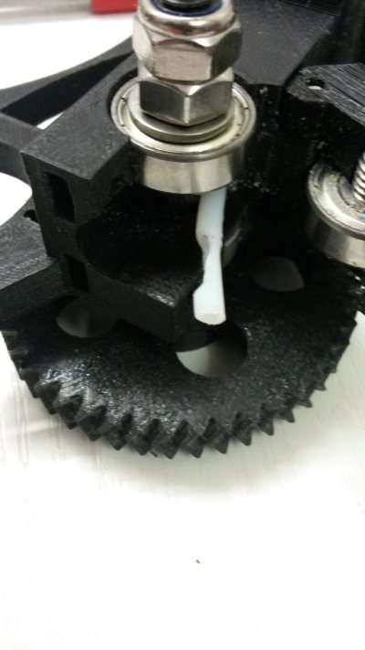
- November 2016, Changed from Greg's extruder to the E3D Titan extruder (original):
Problems:
- the Prusa x-carriage from E3D does not fit the KitPrinter3d (axis are father apart) so I had to make my own (yellow) adapter for the KitPrinter3d x-carriage.
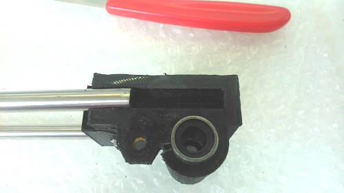
- the lineair bearings were not pushed back enough into the KitPrinter3d x-carriage (solved with a strip between tiewrap and bearing).
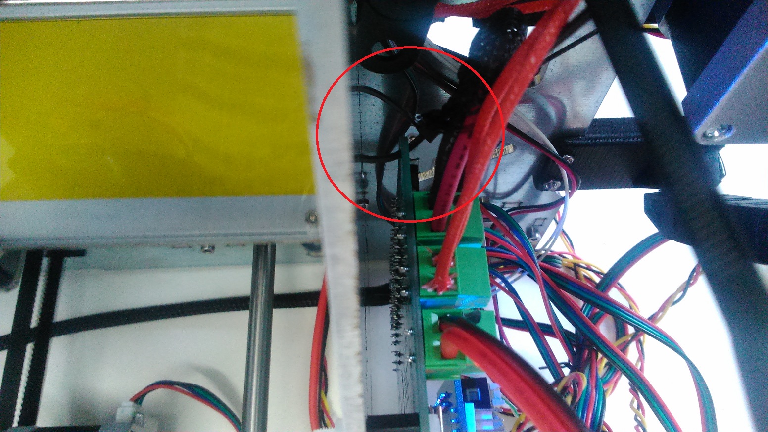
- the lower part of the cable-chain was attached via an adapter to the steel frame but the X-motor jammed into it (see also picture above at 16.). I still have to make a bracket for that.
- the E3D V6's heatblock (V6 bought from KitPrinter3d) does not fit the official teflon socket of E3D. The heatblock is smaller and is probably a Chinese replica.
- Recalibrate extruder feed (see above) at, I think it was, 833.333
- Remove the bolts/nut in AC01 (middle of left/right side), the x-carriage can get stuck on these bolts. And it works without filament jam (1.75mm: do not forget the teflon tube in the idlers top)